
1 Optimize product design
1.1 Optimize mechanical equipment performance indicators
When designing cement mechanical equipments and companies should start from the perspective of cement production technology, constantly optimize the operating parameters of cement machinery and equipment, and optimize the performance indicators of equipment products. This can bring greater economic benefits to customers and improve the brand effect of equipment manufacturing companies.
For example, by adjusting the roller grinding disc speed, powder concentrator speed, system fan speed, air temperature in the mill, humidity of materials in the mill and other roller mill-related parameters, the production capacity of the roller mill equipment can be improved and the quality of the output materials can be improved. On this basis, a large number of on-site operation data of equipment should also be collected.
According to the data, combined with the cement production process analysis, we can further optimize the equipment performance index parameters and improve the equipment quality.
1.2 Optimize the mechanical equipment structure.
In order to improve the quality of mechanical equipment, when designing cement machinery and equipment products, the adjustment needs of cement production process parameters should also be met. By changing the form, size, installation method, etc. of the mechanical equipment structure, the performance and quality of the equipment should be improved.
(1) Select the appropriate roller grinding disc roller (flat roller, conical roller, curved roller), adjust the appropriate height size of the retaining ring, adjust the cross-sectional size and structure of the air ring, etc.
(2) Select the appropriate overall structure of the powder separator rotor, select the appropriate blade structure and size, installation angle and installation form, adjust the air outlet structure size, etc.
1.3 Optimize component structure
When designing cement machinery equipment products, attention should be paid to the structural design optimization of equipment parts. For example, by determining the shoulder R angle of shaft components and optimizing the detailed structural dimensions of components with larger load
(Round corners of castings) can improve the stress concentration of components; by reducing the weight of parts, product manufacturing costs can be reduced; by optimizing the wear-resistant layer material on the roller surface, the wear resistance of equipment can be improved, etc. Things to note when designing the structure of equipment parts are as follows:
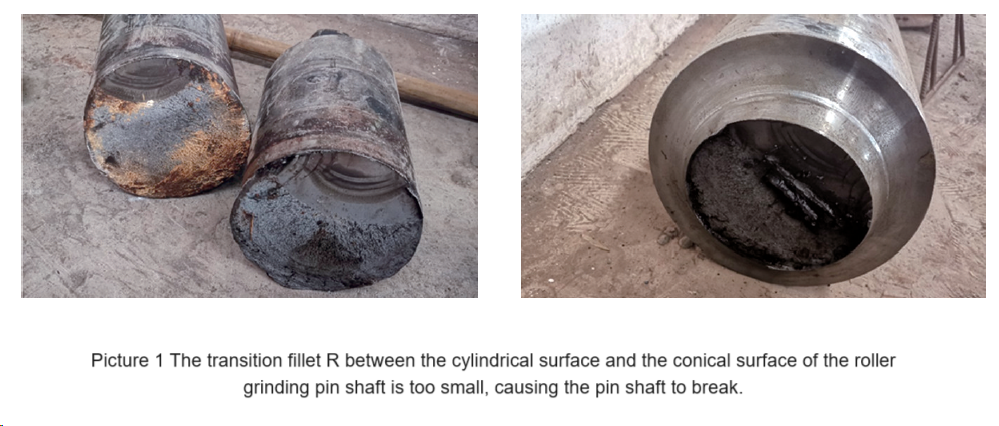
(1) Reasonably select the fillet R of the shoulder of shaft parts and the transition between the cylindrical surface and the conical surface. Choose a larger value as much as possible to avoid premature failure of the shaft caused by large stress concentration at the R corner. For example, if the fillet R at the transition between the cylindrical surface and the conical surface of the roller grinding pin shaft is designed to be too small, stress concentration will occur and the pin shaft will break, as shown in picture 1.
(2) The roller-milled lower rocker arm has both an inner cavity rounded corner R and an outer wall corner (approximately a sharp corner). Defects such as shrinkage holes, cracks, and sand adhesion are prone to occur at the corner of the casting. In addition, when the casting is used, , it is easy to form stress concentration at the corners. Therefore, the corners of the outer wall of the roller-milled lower rocker arm casting should be designed as rounded corners, and the rounded corner R should be selected with a larger value (as shown in picture 2)

(2) The roller-milled lower rocker arm has both an inner cavity rounded corner R and an outer wall corner (approximately a sharp corner). Defects such as shrinkage holes, cracks, and sand adhesion are prone to occur at the corner of the casting. In addition, when the casting is used, , it is easy to form stress concentration at the corners. Therefore, the corners of the outer wall of the roller-milled lower rocker arm casting should be designed as rounded corners, and the rounded corner R should be selected with a larger value (as shown in picture 2). This can weaken the hot spots formed at the sharp corners and reduce stress concentration. degree, making the casting less prone to cracks and eliminating directional crystallization. At the same time, casting round corners is also beneficial to modeling, sand production, and makes the castings beautiful in appearance.
(3) The rotary kiln supporting wheel and the supporting wheel shaft have interference assembly requirements. The two ends of the supporting wheel hole are designed with large rounded corners or transitional inclined cones, which is beneficial to alleviating concentrated stress.
(4) The roller shaft and roller sleeve of the roller press are at the joint surface of the interference fit hole and the end face of the shaft. Pin holes have been drilled through the pin shaft to withstand a certain tangential force and prevent shaft shifting. However, this At the same time, the interference fit effect between the roller shaft and the roller sleeve is greatly reduced. High-quality steel should be selected during design, and should be properly heat-treated to improve the mechanical strength of the material and ensure a tight fit between the roller shaft and the roller sleeve in the interference fit state.
1.4 Reasonable selection of parts and processing accuracy
When designing cement machinery and equipment products, the processing accuracy of parts should be reasonably determined to simplify processing methods, reduce processing procedures, and optimize processing technology.
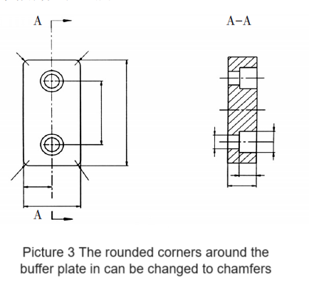
(1) During design, chamfering is used on the outer periphery of some parts, which is more conducive to processing and shaping than using arcs. For example, the rounded corners on the outer periphery of the buffer plate can be changed to chamfers, as shown in picture 3.
(2) When designers design parts, they often select a higher surface accuracy level for parts. This causes manufacturers to improve processing methods to meet parts processing requirements, thus increasing the manufacturing cost of products. Therefore, in design, the design accuracy level should be reasonably selected on the premise of satisfying the performance of the parts.
1.5 Optimize component materials
The material type (steel plate, forging, casting or other materials), material composition and heat treatment method should be selected during design. For example, when selecting the roller material of the roller press, the designer initially used No. 45 steel, then switched to 42CrMo, and added other materials such as Ni alloy to further enhance the strength of the roller. Currently, a new type of high-quality alloy material is used in the design. At the same time, the heat treatment process has been further adjusted, which plays a key role in improving the technical performance of the roller.
1.6 Optimize the selection of supporting equipment
The supporting equipment of cement machinery equipment mainly includes driving equipment (including motors, reducers, coupling devices), hydraulic systems, lubrication systems, control systems, etc. The driving equipment is the core. The optimized driving equipment during design can directly improve the performance of cement machinery equipment.
1.7 Fully understand and apply current standards
Compared with foreign standards, domestic mechanical product industry standards are more comprehensive, while foreign standards are more professional. When designing products, if you want to conduct international benchmarking for a certain product, you need to comprehensively consider all aspects involved in product production (materials, welding technology, non-destructive testing, etc.) and the professional standards of each individual item. For example, in the design of mechanical products, the flat drawing design method is gradually replaced by the three-dimensional drawing design method. In the design process, the dimensions of the parts after generating the two-dimensional drawings, especially the correct use of standards, are based on the mutual coordination of the parts. , it is particularly important to dimension the geometric tolerances.
(1) For large structural parts that have matching requirements with each other, especially the mating surfaces that are not easily observed during the assembly process of parts, it is necessary to reasonably select the matching tolerance and the structural form of the joint surface when it is imported into the assembly (slope, cone). For example, the fit between the rotor bushing and the upper flange of the housing in the roller mill powder separator should be based on the base hole system and clearance fit to facilitate the assembly of the equipment.
(2) Regarding the requirements for the shape and position tolerances of each surface of key parts and their mutual position, the shape and position tolerance values should be selected according to the selection principles of national standard shape and position tolerances, and the reference size positions (which play a key role in the operational reliability of the parts) should be clearly defined. How to mark geometric tolerances, mark combinations, etc. should be paid attention to in the design.
(3) For non-destructive testing of some large forged castings and structural parts, the testing standards recommended by the equipment industry standards should be adopted during design. For example, industry standards are usually used for flaw detection of shaft forgings, and their classification of defect levels is more detailed than national standards, making it easier to determine. For example, the JB/T 5000 standard is a series of standards that almost cover the requirements of various technical conditions involved in type machinery and is the most commonly used technical standard.
2 Optimize product manufacturing process
2.1 Improve processing equipment performance
Improving the performance of processing equipment can transform the processing technology into specialization, functionality, and intelligence, and improve product quality and production efficiency.
(1) Use a robotic welding workstation. Many parts of the trough conveyor can be manufactured using CNC machine tools and forming roller machine tools. The use of robot welding workstations can realize the automation and intelligence of groove plate welding forming, thereby improving the welding quality and work efficiency of products. The robot welding workstation is shown in picture 4.

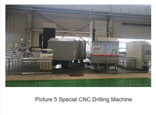
(2) Use special CNC drilling machine tools. At present, roller presses mostly use stud rollers. There are tens of thousands of stud holes on the roller surface. The material of the roller body is high hardness. Special CNC drilling machine tools and high-strength wear-resistant drill bits are used to meet the requirements of efficient and high-quality processing of studs. Nail hole requirements.
The special CNC drilling machine tool is shown in picture 5.
2.2 Use special tooling and assembly lines
(1) Design and manufacture special tool fixtures
The upper and lower rocker arms of the roller mill need to be processed with multiple intersecting vertical holes and surfaces, and there are certain verticality requirements between each surface, which results in more clamping and positioning times for production and processing, and frequent changes in positioning datums. If you design a tooling and process it through one positioning and clamping, you can reduce the errors caused by multiple overturning and clamping positioning, improve processing efficiency and positioning accuracy, and improve product manufacturing quality.
(2) Adopt processing line
Parts such as the air beam of the grate cooler can be processed using special machine tool lines. According to the requirements of the processing procedures, special machine tools are arranged regionally and the parts are transferred by mechanized flow to achieve a close connection between the various processing procedures of the parts. The semi-automatic flow operation method can ensure product quality and improve production efficiency to a large extent. The special machine tool processing line for grate cooler air beam is shown in picture 6.

2.3 Improve product manufacturing process technical documents
Manufacturing process technical documents are programmatic documents that guide the processing and manufacturing of products. They are the rules that producers must follow from product raw material preparation or product blank status to product molding. They are the basis for ensuring product manufacturing quality. Therefore, while using intelligent technology for manufacturing, it is necessary to continuously improve the process and technical document system. The preparation of a rigorous product manufacturing process technical document system is an important guarantee for an enterprise to provide users with high-quality products. It is also an important part of an enterprise’s product production and manufacturing management system. It is a basis for each enterprise to refer to the national standard requirements for mechanical manufacturing processes. It is formulated based on its different product types and manufacturing capabilities.
The types of product manufacturing process technical documents mainly include process documents, process guidance documents, and technical support documents.
(1) Process documents generally include: machining product process cards, riveting and welding process cards, heat treatment process cards, assembly process cards, etc.
(2) Process guidance documents generally include: parts list, paint list, outsourcing parts list, delivery list, special process equipment list, outsourcing production and processing contact sheet, outsourcing tool contact list, and technical contact Orders, material substitution notices, outsourced product inspection and warehousing orders, equipment fixed-length plate material requirements schedules, container shipping notices, key project production progress reports, etc.
(3) Technical support documents generally include: product structure process review records, processing process review reports, process processing codes, technical disclosure records, etc.
2.3.1 Machining product process card
The machining product process card is a document that specifically guides the product processing and manufacturing process. It is generally used in the processing of multi-process or complex parts. For some professional processing processes, such as welding, heat treatment and other processes, the product process card is mostly used. Develop process documents. The machining product process card clarifies the sequence of each process of part processing, the principles and methods of reference positioning of parts, the machine tool specifications used in each process, and the selection of various processing tools and fixtures.
and other matters, are important guiding operating documents for mechanical processing technology.
2.3.2 Assembly process card
The assembly process card is very important for the final shaping of the product. Whether a product can operate safely and reliably is closely related to its assembly quality, and the assembly process card is a guiding document that guides assembly work. The use of assembly process cards can also effectively prevent unqualified parts from entering final assembly products. The assembly process card is mainly used to standardize the assembly sequence of components and put forward specific assembly requirements for key components to avoid affecting the operation of components or damaging components.
2.3.3 Parts list
The parts list contains all material procurement lists for the product (including profile dimensions, part materials, part quantity, and summary of purchased parts) as well as all process flows of product processing. It is the overarching guidance document for all processing documents. All procedures of product production and processing should be carried out under its guidance.
2.3.4 Delivery details list
For building materials machinery and equipment, after all products are processed and manufactured, they are not delivered to the user as a whole, but are assembled into several components and a large number of individual parts for delivery. After each part is processed, some enter the assembly stage, and some enter the factory warehouse to wait for delivery. The process is guided by the delivery schedule. The delivery schedule can also provide data for the preparation of product packing lists, such as the dimensions and weight of assembled components, the quantity and weight of individual parts, etc. The completeness and accuracy of the delivery details list is the guarantee for the complete delivery of the product to the user. It is an indispensable document. The delivery details of different factories have different forms of expression. At present, QR codes are commonly used to identify finished parts, which is very helpful for preparing delivery details.
2.3.5 Processing Code
Process processing codes are regulations that machine tool operators must implement during product processing. They mainly include: operational safety, preparation before processing, tools and clamping, processing requirements, and operating methods of each machine tool.
3 Strengthen product inspection and manufacturing supervision
Product inspection and manufacturing supervision is a very important task, which is related to a series of issues such as product quality, product operation reliability, and whether product performance can be guaranteed.
3.1 Preparation and precautions of product quality inspection plan (QCP)
The product quality inspection plan (QCP) is usually completed by the product manufacturing unit (Party B) after preliminary preparation, and then submitted to the entrusting unit (Party A) for review, modification and joint completion of preparation. This is determined by the formation process of the product manufacturing process, that is, The manufacturing unit prepares the processing technology and
The process nodes for product quality inspection are determined based on the processing process sequence, and the entrusting unit proposes inspection rules and standards based on the performance requirements of the processed products. The preparation of QCP must meet the integrity of the product processing and manufacturing process. After final confirmation, it will be included in the technical documents of the product supply contract as a binding clause of the contract. The following matters need to be noted when preparing QCP:
(1) Incorporate the quality inspection of all key and major components in the product into QCP.
(2) According to the processing and manufacturing process, clarify the quality inspection process section 25 equipment technology.The standards and levels adopted for inspection shall be determined by each participating witness.
(3) Clarify the items to which the parts belong, the equipment to which they belong, and the components to which they belong, as well as the material of the parts, the part drawing numbers corresponding to the parts, etc.
(4) Covers types of inspection control, such as clear dimensional inspection, non-destructive inspection and other inspection types (not limited to this).
3.2 Clarify the special terms of the technical text in the contract
When signing a supply contract, signing technical terms is an important part of ensuring product quality. In addition to clarifying the scope of supply and acceptance standards according to the drawing design requirements, some special terms not included in the drawing design will generally be added, such as: product appearance quality, painting, packaging requirements, etc., which should be included in the supply contract when signing the contract. This must be clearly stated in the goods contract and must also be taken seriously during the product supervision process.
3.3 Control inspection time nodes
In addition to product quality inspection according to the time points specified in the QCP, on-site supervision and inspection of intermediate links of a certain process in the product processing process are also required, such as supervision of the pouring process of large castings. Since there are certain difficulties in the smelting and pouring of molten steel during the manufacturing process of large castings, and the probability of defects is relatively high, it is necessary to conduct on-site supervision and inspection of the pouring process. On-site supervision and inspection of the production process also includes inspection of important parts
Inspection of the separation, marking, storage, and transfer of random samples. These processes should be confirmed on-site in a timely manner. This can be completed by taking photos and videos on-site. Later, on-site confirmation will be conducted to ensure the performance of the workpiece and sample materials. consistency.
3.4 Inspection precautions
(1) Before measuring the dimensions of the workpiece, check the inspection and calibration records of the measuring instrument to confirm that the calibration date is valid.
(2) Pay attention to the temperature of the parts being measured and the ambient temperature. The measurement results are different under different ambient temperatures, and the newly processed workpiece should not be measured immediately.
(3) Pay attention to the clamping method of the measuring instrument. Holding the measuring instrument for too long will affect the measurement accuracy. The inner diameter micrometer rod measures the inner hole of the workpiece as shown in picture 7.

(4) The hydraulic system should not only detect the system pressure, but also separately detect the key components in the system (hydraulic cylinders, various valves, etc.), and pay attention to the oil used.
3.5 Key points of product manufacturing supervision
(1) Be familiar with the relevant technical terms of the sub-delivery contract, and clarify the drawing design requirements, inspection items, inspection standards, etc. for supervision and inspection of parts.
(2) Understand and master the product production plan, especially the production schedule of parts and components, and conduct on-site finished product process inspection in a timely manner.
(3) Based on the management status of the manufacturer, raise questions in a timely manner to ensure product processing quality.
(4) Communicate frequently with operators to master accurate information and control product quality.
(5) Frequently assist operators in measuring work and improve the inspection level of manufacturing supervisors.
(6) For large and complex welded structural parts, manufacturing supervisors need to conduct in-depth and detailed observations, focusing on easily overlooked parts, to ensure the internal and external quality of the components.
3.6 Key points for manufacturing supervision of cast and forged parts
(1) Castings: focus on molten steel smelting, pouring process (temperature control, riser setting), riser cutting (remaining dimensions), sample collection (position, quantity), heat treatment methods (annealing, normalizing).
(2) Forged parts: focus on the source of steel billet (ordinary molten steel, refined molten steel), forging method (free forging, die forging, ring ring forging), heat treatment method (normalizing, quenching, quenching and tempering), rough processing of the blank ( Chamfer ≮ 2mm), sample collection (location, quantity).
(3) Welded structural parts: focus on welding stress relief treatment methods (heating aging method, vibration aging method), corner trimming, welding slag removal, internal weld inspection, and treatment of welds at the intersection of three surfaces.
(4) Rollers with holes: focus on the finishing of the hole size surface with matching tolerance requirements (preferred in order are internal grinding machine grinding, honing, and abrasive belt grinding). Ultrasonic flaw detection should be performed before finishing each surface. Magnetic powder Flaw detection should be carried out after the surface finishing is completed and before the outer surface is smoothed.
(5) Shaft parts (including integral rollers): focus on surface finishing processing to match the size (preferably cylindrical grinder grinding, pressure roller, abrasive belt grinding in order), finishing processing of the inner R at the step (pressure roller, Abrasive belt grinding), ultrasonic flaw testing should be performed before finishing each surface, and magnetic particle testing should be
It is carried out after the surface finishing is completed and before the outer surface is smoothed.
(6) Large reducer: The main processing procedures of gears (including gear shafts) are turning, gear hobbing, and heat treatment. The heat treatment includes tooth surface heat treatment, finishing, and gear grinding (shaft grinding); focus on the box and planet carrier types. Inspection after finishing; gear inspection includes dimensional inspection, tooth profile inspection (tooth profile detector), ultrasonic flaw detection and magnetic particle inspection, tooth surface hardness (tooth surface hardness tester); after finishing of the box and planetary carrier, it is required Use a three-dimensional coordinate detector or check the three-dimensional position size on a machine tool.
(7) Large hydraulic cylinder: The cylinder finishing uses deep hole drilling, deep hole boring or turning, and honing (honing machine); the piston rod and shaft parts are processed in the same way; the cylinder inspection items include size, roughness, geometric tolerance, ultrasonic wave Flaw detection and magnetic particle inspection; oil pressure test after assembly of the oil cylinder.
3.7 Key points for manufacturing supervision during assembly process
(1) Before assembly, the parts need to be cleaned, flash and burrs removed, and the parts should be ground and chamfered according to the assembly process requirements.
(2) Bearing assembly: Inspect the bearing model and check the lower clearance at room temperature. Oil bath heating is generally the first choice for heating, followed by electromagnetic induction heating. Electric furnace heating can also be used. Flames cannot be used to heat the bearing directly.
(3) Oil lines and oil pipes: Check the welding, bending, rust removal and washing of pipe joints, check to complete the pressure test and cleaning of pipe fittings and seal them properly.
(4) Lubricating oil: Check the filling status of grease lubrication, whether the thin oil lubricating oil path is smooth, etc.
(5) Seals: Check whether the seals are complete and not damaged, whether the self-made parts are standardized, and check the sealing performance.
(6) Interference fit components: Pay attention to heating methods, temperature control, and positioning control during assembly (such as the axial positioning of roller mill rollers and wheel hubs).
(7) Parts with grinding matching requirements: Check the distribution and range of contact points of the grinding parts.
(8) Check whether there is interference or collision between relatively moving parts.
(9) Rotor parts (especially welded structural parts) need to undergo dynamic balancing experiments.
3.8 Appearance quality inspection
(1) Check the grinding status of the casting fillet and check whether there are any casting defects on the inner and outer surfaces of the casting with the cavity.
(2) For large shaft parts that are to be quenched and tempered, ensure that there is a 2~3mm chamfer on the shoulder after rough machining to avoid stress concentration and micro cracks during the heat treatment process.
(3) The exposed cutting edges, flash burrs, etc. of the welded structural parts are all polished and smoothed using a grinder, and the chamfer is generally 2~3mm.
(4) The surface formed by welding thin steel plates should not have knock marks, so as not to affect the appearance quality and reduce product quality after painting.
(5) After the product is formed, the appearance should be clean and tidy, with no scratches, bumps, residue, sharp corners, paint peeling, etc.
4 Improve product coating and packaging
4.1 Coating of products
4.1.1 General principles for product coating
All product defects cannot be treated by applying putty. The outer surface of castings must be trimmed with a polisher to improve the apparent quality of product parts (including castings, welded structural parts, etc.). The method of applying putty to the fan connecting flange is shown in picture 8.

During the shipping (or temporary storage) process, the surfaces of shaft parts, rotary kiln belts, large ring gears, etc. are exposed (usually with protective covers), and the coating effect on their surfaces will directly affect the quality of the parts. Therefore, the surface of the shaft should be made of rust-resistant and corrosion-resistant coating materials that are different from other surfaces, and should be easy to remove during on-site installation.
4.1.2 Precautions for coating inspection
(1) Coating materials: Carefully check whether the brand and color code of the coating materials used are consistent with the contract requirements.
(2) Coating method: mainly spraying, with brushes used for individual parts
Supplement.
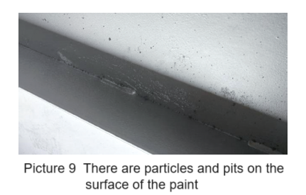
(3) Before painting the surface of the parts, carefully check whether there are any remaining debris, whether it is smooth, and whether the surface of the structural parts has been rust-removed. If the dust, sand, etc. on the casing is not cleaned, spray paint, resulting in particles and pockmarks on the surface of the paint film, as shown in picture 9.
(4) Carefully check whether there is unevenness, paint leakage, or sagging during the paint spraying process, and whether corners and hidden areas are sprayed in place. The paint sagging caused by uneven spraying is shown in picture 10.

(5) Check the bolt holes. The hole walls of exposed bolt holes must be painted, and the bolt holes on the flange cover should be removed and painted after the assembly work is completed, and then reassembled and painted as a whole.
(6) Check the paint film thickness. This is the final inspection after painting is completed. The paint thickness gauge should be used correctly. The paint film thickness should neither be less than the contract requirements nor too thick.
(7) In principle, the use of putty to repair the surface is not allowed.
4.2 Product packaging
4.2.1 General principles of product packaging
(1) During the packaging process of the product, all parts of the same component should be gathered together. Even parts of the same specification, as long as they do not belong to the same component, must be packaged separately. This will facilitate on-site installation to ensure the integrity and ease of parts. Find.
(2) For export products, use containers for packaging as much as possible, which will help protect parts from damage and save shipping costs.
(3) Properly package the bare components, pay special attention to the extension length of the extension parts in the bundle, and try not to extend or shorten the extension size to avoid increasing shipping costs.
(4) Check whether the production and use of the packaging box match the packaged items, for example, whether there is extra space and whether there is enough strength to carry the packaged items.
(5) The packaging box should be able to withstand a certain pressure load, have good sealing, and be suitable for lifting and forklift transfer.
4.2.2 Precautions for packaging inspection
(1) The wood used in packaging boxes may contain insect pests, germs or other harmful organisms. It is necessary to verify whether the wood used for packaging has been fumigated and carefully check the fumigation records.
(2) For the lifting of packaging boxes, it is necessary to check the signs of the lifting parts of the packaging boxes and confirm whether the corners and special lifting rings used for the lifting points are standardized.
(3) During the packing process, in addition to checking whether the loaded products are consistent with the parts listed on the packing list, photos must be taken by layer and records must be kept.
(4) When printing or affixing marks on the packaging box, it is necessary to carefully check whether the form and content are correct and whether they are consistent with the packing list.
(5) Some other markings are usually sprayed on the packaging box: such as the number of stacking layers, fragile, rainproof, moisture-proof, etc. The required spraying on the surface of the packaging box must be determined based on the form of the packaging box and the characteristics of the packaged items. type of identification